basic thermostat wiring diagram
WIRING THE BOILER The load is now a boiler. Click the icons below to get our NEC compliant Electrical Calc Elite or Electric Toolkit available for Android and iOS.

Electric Oven Thermostat Wiring Diagram And Basic Oven Wiring Diagram Wiring Diagrams 17 El Baseboard Heater Baseboard Heater Thermostat Thermostat Wiring
Usually a red and a white wire.

. Automatic UPS system wiring circuit diagram for Home or Office. A short summary of this paper. The kits are installed at the HVAC control board.
Older telephone wiring was a basic Cat-3 4 conductor or 2-pairs with red green black yellow. The Complete Guide to Electrical Wiring. To protect your equipment turn off the power at the breaker box or switch that controls your heating and cooling equipment.
10si Alternator Wiring Diagram All of the wiring diagrams I have seen have a wire from through Hook the 1 alternator terminal to ACC and the tractor coil power to IGN. See the best latest Honeywell Alarm Panel Codes on. You can start comparing and weighing your options based on the top products weve listed earlier.
You can run 1810 thermostat wire which gives you additional wires for a potential outdoor sensor. Please follow the below guide for the basic wiring walkthrough. To make sure that your system is off change the temperature on your existing thermostat so that your system starts heating or cooling.
This additional terminal is labeled G in the thermostat. It is onoff switch which controls the swing motor responsible for controlling the movement and direction angle in which the air. Manual UPS Wiring Diagram With Change Over Switch System.
An add-a-wire kit allows your thermostat to use your existing wires and still get constant power without using power stealing. Honeywell alarm panel wiring diagram. Familiarize with Standardized Electrical Symbols Knowing the meanings of basic electrical symbols in your electrical drawing will help you quickly understand and troubleshooting the circuit.
Installation requires a screwdriver and the ability to read a wiring diagram. 2 Wire Thermostat Wiring Furnaces The most basic thermostat has 2 wires. For instance for a gas furnace to turn on the heat the thermostat internally connects the R terminal power to the W.
Color of Wire and Termination. Wiringwiring a Thermostat. Multiple GFCI Outlet Wiring Diagram - pdf 72kb Back to Wiring Diagrams Home.
How to Read A Electrical Drawing 1. Aside from knowing RV thermostat wiring diagram if choosing a model that you need to hardwire you also have to figure out if the unit youre buying can operate on batteries or hardwired. Wiring Landscape Lights Wiring Landscape Lights Get a basic knowledge of how to do wiring on landscape and garden lights.
6 Full PDFs related to this paper. If you have a two-stage heat pump then you will also utilize terminal Y2 for the second stage. It is a red wire and comes from the transformer usually located in the air handler for split systems but.
This is fine if the boiler is 120 V. This type of diagram is like taking a photograph of the parts and wires all connected up. Basic Wiring for Motor Contol Circuitry of a Starter Two-Wire Control Two-Wire Control circuits or Low Voltage Release One of the common control wiring circuits used is known as Two-Wire or Low Voltage Release LVR.
Thats why we only need two wires. A rotating Thermostat switch work as onoff switch for the compressor its status is depending on what temperaturecooling degree you set it at usually there are 8 positions for cooling degree. I purchased a Wifi thermostat and I have a basic understanding of the wiring but I have a couple of issues.
Youll have to remove the access panel to your furnace to locate the panel. When it comes to the Honeywell thermostat wiring heat pump you are wiring the heat pump thermostat over to the indoor wire handler you going to typically run 188 thermostat wires. White wire for heating.
In the most basic system this functionality is provided by use of a fan center relay and the low voltage wiring to the thermostat now will require a minimum of three wires for heat only units and four wires for heat cool fan for control. In the US The 240V Single phase load can be connected to two phases without a Neutral wire. Wiring VOIP Telephone.
Home Wiring Diagrams from an Actual Set of Plans. D Somewhere on the back of the refrigerator usually very high or very low or possibly on any wiring diagram that may be pasted to the back of the refrigerator. A lamp is usually represented as a circle with a cross inside it.
Wire a Dryer. Wire a Dryer Cord How to Wire a Dryer Cord How to change over from a 3-prong dryer cord to a 4-prong dryer cord. Two wire thermostat wiring is used for furnaces only and usually doesnt need a C or Common wire.
Heat pump thermostat wiring chart. Inside my old thermostat I have a white wire on O a red wire on R 24 v as measured at the air handler and my yellow and green wire are on W with a jumper to Y. This telephone wiring diagram shows the standard wiring for Telephone Jacks explaining the wiring connections for.
This diagram shows how to wire a Delco GM internally regulated 3-wire alternator. It utilizes a main-tained contact type of pilot device such as a thermostat float switch or presence sensor. See Figure 4 page 20 This wiring diagram shows 120 V coming from L1 of a circuit breaker through a switch powering a boiler control and returning through L2 back to the neutral bar of the circuit breaker box.
This confuses me as I dont understand the 3 wires together. That is a basic Honeywell thermostat wiring diagram for a single-stage heat pump. Typical wiring diagram for heatcool 4-wire single transformer systems TRANSFORMER Heating System Fan Relay Cooling System RC JUMPER WIRE B O.
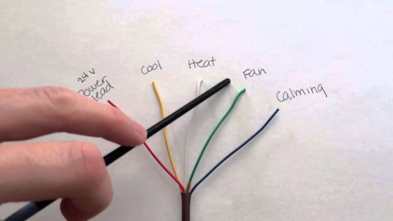
R The R terminal is the power. Wire A Thermostat How to wire a thermostat thermostat wiring color codes and wiring diagrams. This electrical wiring project is a two story home with a split electrical service which gives the owner the ability to install a private electrical utility meter and charge a renter for their electrical usage.
The Electrical Calc Elite is designed to solve many of your common code-based electrical calculations like wire sizes voltage drop conduit sizing etc. Red wire for power 24h. Furthermore this thermostat wiring diagram is specifically for a system with two transformersYour system likely only has one transformer as most typical residential systems only use a single transformer for control.
When the current passes through the lamp it will produce light. Automatic UPS system wiring circuit diagram for Home or Office New Design With One Live Wire Automatic UPS System Wiring Diagram in Case of some items depends on UPS and rest depends on Main Power at Office or Home. Typical wiring diagram for cool only 3-wire single transformer systems Cooling System Fan Relay B O RC JUMPER WIRE Y RH 24 VAC 120 C Hot Neutral THERMOSTAT SYSTEM G W Figure 4.
Full PDF Package Download Full PDF Package. At its most basic your thermostat connects terminals via internal relays to send power to these different wires to control your HVAC system. In Three Phase Supply motors and large electric heaters can be directly connected to the three Phases Neutral is not needed in all cases while in Single Phase load circuits light fan etc can be connected in between Phase and Neutral through proper protective devices eg.
E If you absolutely cannot find a metal nameplate some refrigerators have a paper sales sticker left on just inside the door. Thermostat Wiring and Wire Color Chart Thermostat Wiring Colors Code.

Thermostat Wiring Explained April 26 2011 By The Internet Electrician Sharetweet 1mail In This Article I Am Going T Thermostat Wiring Hvac Thermostat Hvac

New Basic Engine Wiring Diagram Wiringdiagram Diagramming Diagramm Visuals Visuali Thermostat Wiring Electrical Wiring Diagram Electrical Circuit Diagram

Wire A Thermostat Thermostat Wiring Home Electrical Wiring House Wiring

Thermostat Wiring Explained Thermostat Wiring Refrigeration And Air Conditioning Hvac Thermostat

Heat Pump Thermostat Wiring Chart Diagram Single Stage Heat Pump Wiring Diagram Thermostat Wiring Heat Pump Hvac

Thermostat Wiring To A Furnace And Ac Unit Color Code How It Works Diagram Youtube Thermostat Wiring Hvac Thermostat Thermostat Installation

Sensi Thermostat Wiring Diagram Download Honeywell Thermostat Wiring Diagram Download Thermostat Wiring Digital Thermostat Thermostat

Unique Trane Heat Pump Thermostat Wiring Diagram Thermostat Wiring Trane Heat Pump Electrical Diagram
Air Conditioner Thermostat Wiring Diagram Awesome Stunning Lennox At New Furnace Electrical Wiring Diagram Thermostat Wiring Electrical Circuit Diagram

Furnace Thermostat Wiring And Troubleshooting Thermostat Wiring Hvac Thermostat Thermostat
Thermostat Wiring Color Code Decoded Youtube Thermostat Wiring Color Coding Diagram Design

Thermostat Wiring Explained April 26 2011 By The Internet Electrician Sharetweet 1mail In This Thermostat Wiring Refrigeration And Air Conditioning Furnace

Goodman Air Handler Wiring Diagram Inspirational Thermostat Wiring Air Handler Goodman Heat Pump

Cool Intertherm Thermostat Wiring Schematic Photos Pumps Material Electric

House Thermostat Wiring Diagram Thermostat Wiring Hvac Thermostat Thermostat

Heat Pump Thermostat Wiring Explained Colors Terminals Functions Voltage Path Youtube Thermostat Wiring Heat Pump Thermostat

Thermostat Heat And Cool 2 Transformers Thermostat Wiring Refrigeration And Air Conditioning Electrical Circuit Diagram

Diagram Diagramsample Diagramtemplate Wiringdiagram Diagramchart Worksheet Workshe Basic Electrical Wiring Electrical Circuit Diagram Electrical Diagram

Thermostat Wiring To A Furnace And Ac Unit Color Code How It Works Diagram Youtube Thermostat Wiring Hvac Thermostat Thermostat Installation